Procedural 3D Meshes in Substance3D Designer

General / 22 July 2024

The MV Mesh Tools - Utilities

The MV Mesh Tools - Utilities offer a suite of tools and utilities to import, edit and render 3D meshes in Substance 3D Designer. While keeping everything procedural no need to bake textures or mesh information anymore. See the Plugin in action here.


Node Reference

To get you started with the plugin, here are all the Nodes and how to use them, you can find the complete Node-Reference also here.

Import a 3D mesh into Designer

The plugin imports the 3D data of an .obj file as an image and creates a bitmap node in the Substance3D Designer graph.


The MV Mesh Tools - Input Node

generates the 3D mesh by directly inputting vertex, UV, and normal coordinates, as well as the corresponding face indices, following the .obj file format specification.


The MV Mesh Tools - Render Node

converts the input scene into a rendered texture. This allows visualizing 3D meshes as 2D images.


The MV Mesh Tools - Add Node

combines the mesh data of two scenes or meshes into a single scene. This allows you to keep multiple meshes separate within the same scene.


The MV Mesh Tools - Array Node

creates multiple copies of a mesh or an entire scene along the x, y, and z axes. This allows the efficient creation of repeated structures or patterns.


The MV Mesh Tools - Transform Node

performs basic transformations to a mesh or scene, including translation, rotation, and scaling.


The MV Mesh Tools - Displace Node

modifies the vertex positions of the meshes in the input scene using a displacement map. This is useful for adding fine details and textures to the geometry of the meshes.


The MV Mesh Tools - Morph Node

blends the vertex positions between two meshes. It is important that both meshes have the same number of vertices and identical face indices.


The MV Mesh Tools - Sampler Node

samples multiple textures to influence the position scale, and rotation of a mesh or scene. This allows dynamic and texture-driven transformations of 3D objects.


The MV Mesh Tools - UV-Grid Node

is a helper node designed to draw the UV maps of the meshes of a scene. It helps visualizing and position textures accurately by providing a clear representation of the UV coordinates.


The MV Mesh Tools - UV Transform Node

applies transformations to the UV maps of the meshes in a scene. This allows adjusting the UV coordinates for various effects, such as scaling, rotating and translating textures applied to the meshes.


The MV Mesh Tools - Texture Mapping Node

uses the UV map generated by the MV Mesh Tools - Render Node to apply a texture to the meshes in a scene. This allows precise control over how textures are applied to 3D models based on their UV coordinates.


The MV Mesh Tools - Material Mapping Node

uses the UV map generated by the MV Mesh Tools - Render Node to apply material maps to the meshes in a scene. This allows precise control over how the material is applied to 3D models based on their UV coordinates.


Get the plugin from my artstation store https://www.artstation.com/a/21868974

Get the plugin from gumroad https://marcovitale.gumroad.com/l/mvmeshtools

If you have any feedback or feature requests, please let me know.

Stay healthy and creative

Marco Vitale

Convolutional Neural Network in Substance 3D Designer

Making Of / 21 January 2024

The Project

Neural Networks are kind of these scary mighty blackboxes. That was the reason, why I took a deeper look into that topic, researching all kinds of neural networks. After weeks of reading papers and documetations, I tested the first models using PyTorch. It's pretty easy to use this framework to create even complicated deep networks, without knowing how it's working under the hood.

It was time for nodevember, so I challenged myself and wanted to find out, if it's possible to implement a fully functional convolutional neural network in Designer?

The answer is YES! I managed to implement all the layers of the famous VGG16 Model from scratch using the pretrained weights from the original model trained on the ImageNet dataset predicting 1000 different classes.

The result is probably the largest graph I've ever done. The size of the graph is 86851px x 2148px (Substance 3D Designer didn't render the whole graph so I had to find a workaround for showing the graph as well). I also created a set of nodes, which I will publish soon, to create your own neural networks in Designer.

Breakdown

Before we go through a detailed breakdown, some impressive statistics about the graph:

  • 8,488 Pixelprocessors
  • 4,225 Valueprocessors
  • 138,357,544 Trainable Parameters using 527.79MB of memory
  • the total size of the .sbsar is 594.65MB
  • time to compute the node around 3.5 seconds

A short introduction into the VGG16 Network 

VGG16 Model is a deep convolutional neural network architecture known for its simplicity and effectiveness in image classification tasks. Developed by the Visual Geometry Group (VGG) at Oxford, it consists of 16 weight layers, including 13 convolutional layers and 3 fully connected layers. The network's uniform structure with small 3x3 convolutional filters helps in learning hierarchical features. Despite its depth, VGG16's straightforward design makes it a widely used and referenced model in computer vision.

The total learnable parameters in VGG16 is 138,357,544:

  • Convolution Block 1: 2 • (3 • 3 • 3 • 64 + 64) = 3,840
  • Convolution Block 2: 2 • (3 • 3 • 64 • 128 + 128) = 221,440
  • Convolution Block 3: 3 • (3 • 3 • 128 • 256 + 256) = 1,475,840
  • Convolution Block 4: 3 • (3 • 3 • 256 • 512 + 512) = 5,899,776
  • Convolution Block 5: 3 • (3 • 3 • 512 • 512 + 512) = 11,783,424
  • Fully Connected Block: 102,764,544 + 16,781,312 + 4,097,000

This makes VGG16 a relatively extensive network with a large number of parameters, even by today’s standards. However, the simplicity of the VGGNet16 architecture is its main attraction.

The VGG16 Model Architecture

The architecture of the Model consists of 5 Convolution Blocks, after each convolution block, a pooling layer reduces the size of the input. While the size is reduced to a quarter of the input of the layer, the depth gets doubled. This technique reduces the spatial dimension of the feature maps until almost every spatial information is gone and the result is a 25088 element long feature vector. The fully connected layers reduce this giant vector to a size of 1000 output classes.

to better understand, the reduction of the spatial dimension, I made a 3D visualisation of the models architecture:

What is convolution

Convolution is a mathematical operation that combines two functions to produce a third function. In the context of image processing and deep learning, convolution is often used to process and analyze data. In the case of discrete convolution, which is commonly employed in digital signal processing and deep learning, it involves an element-wise multiplication of two arrays followed by a summation. Convolution in image processing is often used to filter an image, for extracting features like edges, corners, blurring or sharpening.

Substance 3D Designer has a node which can handle these operations very well, by using the GPU - the Pixelprocessor, that's why I started to implement the network with only Pixelprocessors.

The discrete convolution between the Input Image and the Kernel is calculated as follows:

Substance 3D Designer implementation

The convolution operation in a neural network works very similar, except the input image and the kernels are 3-dimensional, so basically the input image has a depth-component as well as the kernel. These 3-dimensional Arrays are called tensors.

In Substance 3D Designer this can easily get performend in a pixel processor, the problem is, that image textures in Designer can have a maximum of 4 channels (R, G, B, A). For a network like this I needed a possibility to store more than 4 channels of an image, since the output layers have 64, 128, 256 and 512 channels.

The idea was to flatten the depth channels and reducing the third dimension to a 2-dimensional image. This is achieved by creating a texture, where each channel of the feature maps is flattened out and stored in the same image texture next to each other, this is the red, green and blue channel. of the input image, side by side in one texture.

The coefficients (weights) of the convolution is also stored in a layout like this, so it is actually quite simple to convolve the input with the kernels in one Pixelprocessor. it convolves a 3-dimensional input with a 3-dimensional kernel, outputting a single 2-dimensional channel of the feature map. In order to produce another 3-dimensional "tensor" this step is repeated for every output-channel.
After packing all the feature channels the same way as shown before, the result of the first layer is this:

The second convolution layer, performs another pass over all the feature maps, every convolution filter learns to extract other features, like edges, corners, contours and so on.

Following the models architecture, this process is repeated until the end of the block, the pooling layer is then used to reduce the spatial size of the feature-maps. This can also be done in a Pixelprocessor.

The resulting feature maps:

This gets repeated until the last Pooling Layer, here are the resulting feature maps, for each layer of the network

After the last Convolution Block, all features get flattened out in a 1x1x25088 element big vector. For this I also used a Pixelprocessor

After the flatten layer, three fully connected layer reduce this feature vector until there is only one feature highlighted. This Operation is basically a Vector - Matrix - Multiplication performed by two Pixelprocessors:

Conclusion

Since this was a personal challenge the graph needs a lot of cleanup before I can share it publicly, so please have some patience but I will upload the complete framework of nodes created for CNNs soon. Until then I uploaded the .sbsar, the high resolution image of the graph and a list of available classes to GoogleDrive feel free to download it and play with it as much as you want.

Thank you for reading, if you have questions or feedback, or is something is missing in this post, just leave a comment below.

Stay healthy and creative Marco

Tilesafe Rotation in Substance Designer

Tutorial / 05 January 2022

The Problem

When you are working with Substance Designer one of the main goals is to keep your material and textures tileable. Designer offers a lot of tools which keep your tiling intact. But when you rotate a noise or Grunge-Map, you will run into problems. 

Designer provides a node which helps you with that as well, it's called Safe Transform, with that node you can easily rotate the input and keep it tiling.

It works great with angles like 0°, 45°, 90°, 135°, 180°, 225°, 270°, 315°, 360°

What if you want to rotate your input by lets say 26.5651°?It will break the tiling.


The Goal

In this tutorial I'll show you a way to rotate the input by a much larger number of angles and keep the tiling of the texture.


The Method

The method we are using is quite simple and follows these 4 Steps

  • Take the unrotated texture and tile it horizontally and vertically multiple times
  • Rotate the tiled image
  • Find the smallest repeatable piece of the rotated image (This is where a little math comes into play)
  • Crop the image into the size of the tileable piece

The Math

Like I already threatened you there is a little math involved here, but don't be afraid, it's very simple geometry. At the end of this section you'll get an easy to use collection of formulas ;-)


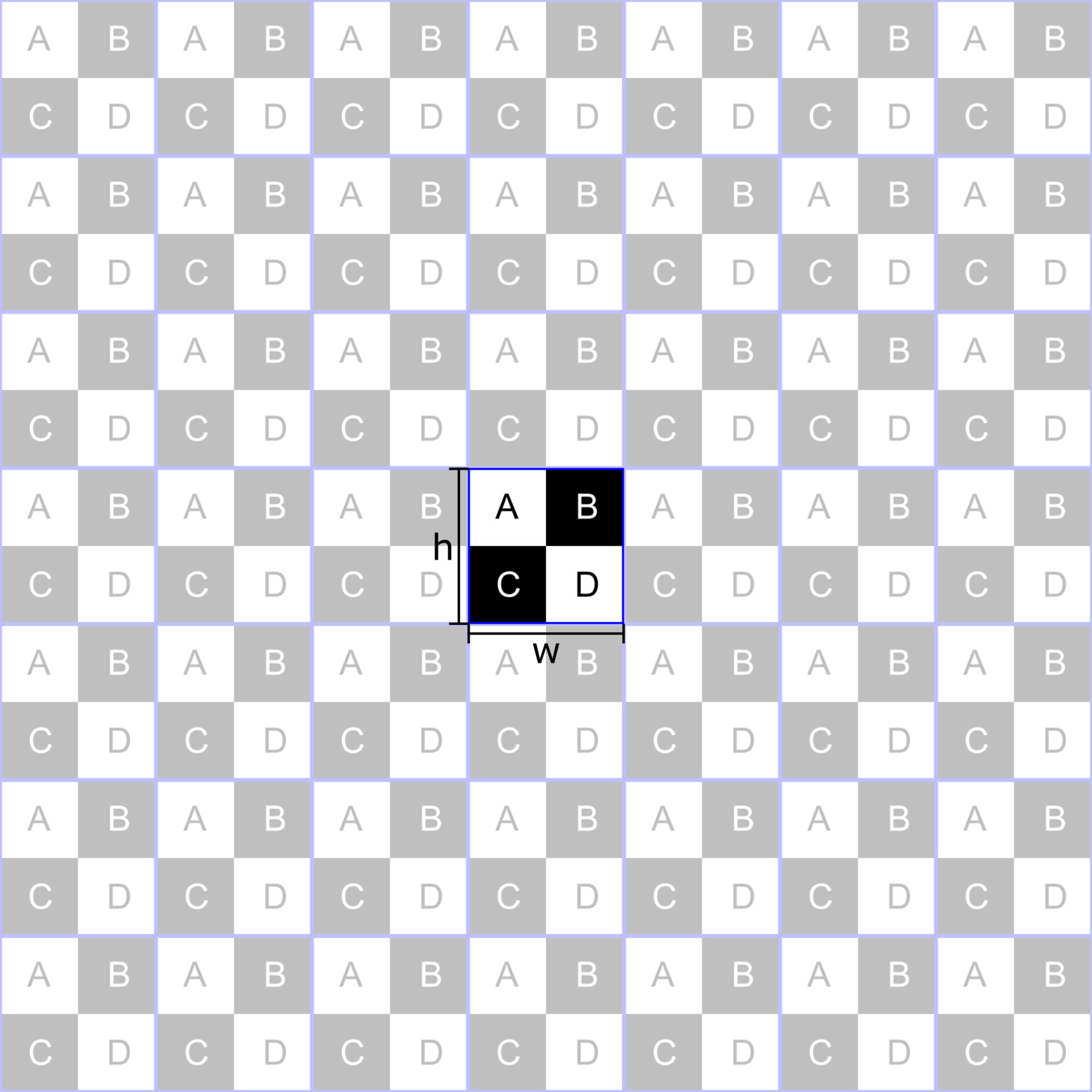
Step 1 - Take the unrotated texture and tile it horizontally and vertically multiple times (here the tiling is 7)

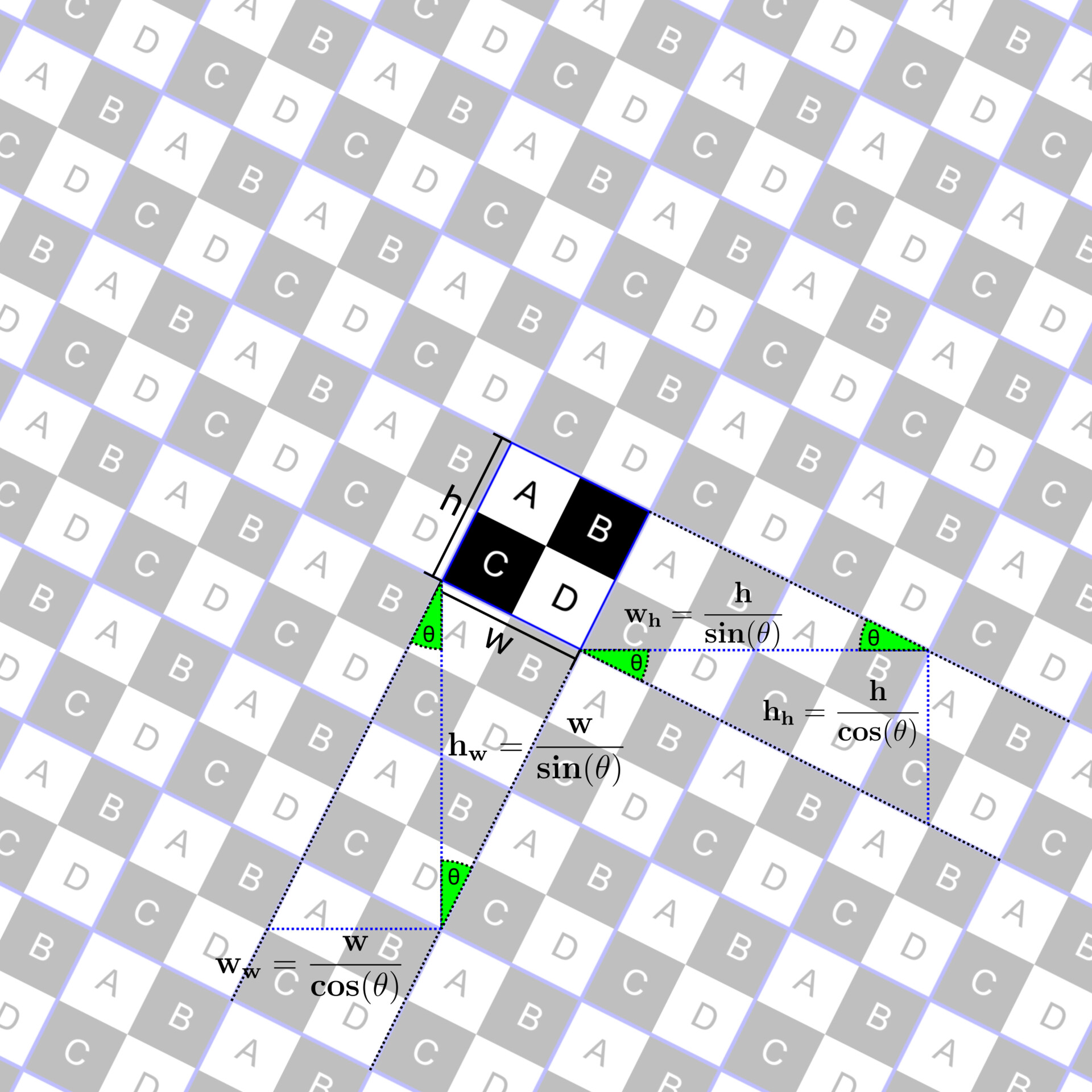
Step 2 - Rotate the tiled image (in this case by 26.5651°)

Step 3 - Find the smallest repeatable piece of the rotated image. We calculate h_h, h_w, w_h, w_w with the formulas provided at the end of the section.

We can simplify it a little, since we are working with a square texture we just need to calculate h_h, w_h. When we are done with these calculations we find the reduced fractions that correspond to (h_h / h_w) and (w_h / w_w). 

Be careful, if these are not rational, you won't be able to find reduced fractions which make sense, so you will not be able to find a width and height which is tileable.

Here we have to use a little trick, the tangens of the rotation angle should be rational, to achieve this we use a rational fraction to derive the rotation angle. So basically we choose a integer ratio between h_h and w_h before we do all the calculations.

Here are some examples:

Angle        tan
5.71059°     1/10
11.3099°     1/5
14.0362°     1/4
18.4349°     1/3
26.5651°     1/2
33.6901°     2/3
45.0000°     1/1
56.3099°     3/2
63.4349°     2/1
71.5651°     3/1
75.9638°     4/1
84.2894°    10/1

I made a Spreadsheed with a lot of angles with rational fractions, to help you with this. Just open this Google Doc

Step 4: Crop the image into the size of the tileable piece


Formulas

Now you have everything you need to create a rotated tileable texture in Substance Designer but Substance Desinger provides us with the Pixelprocessor, so we are able to create a elegant node, which does this whole math, rotating, cropping, tiling for us.


The Implementation

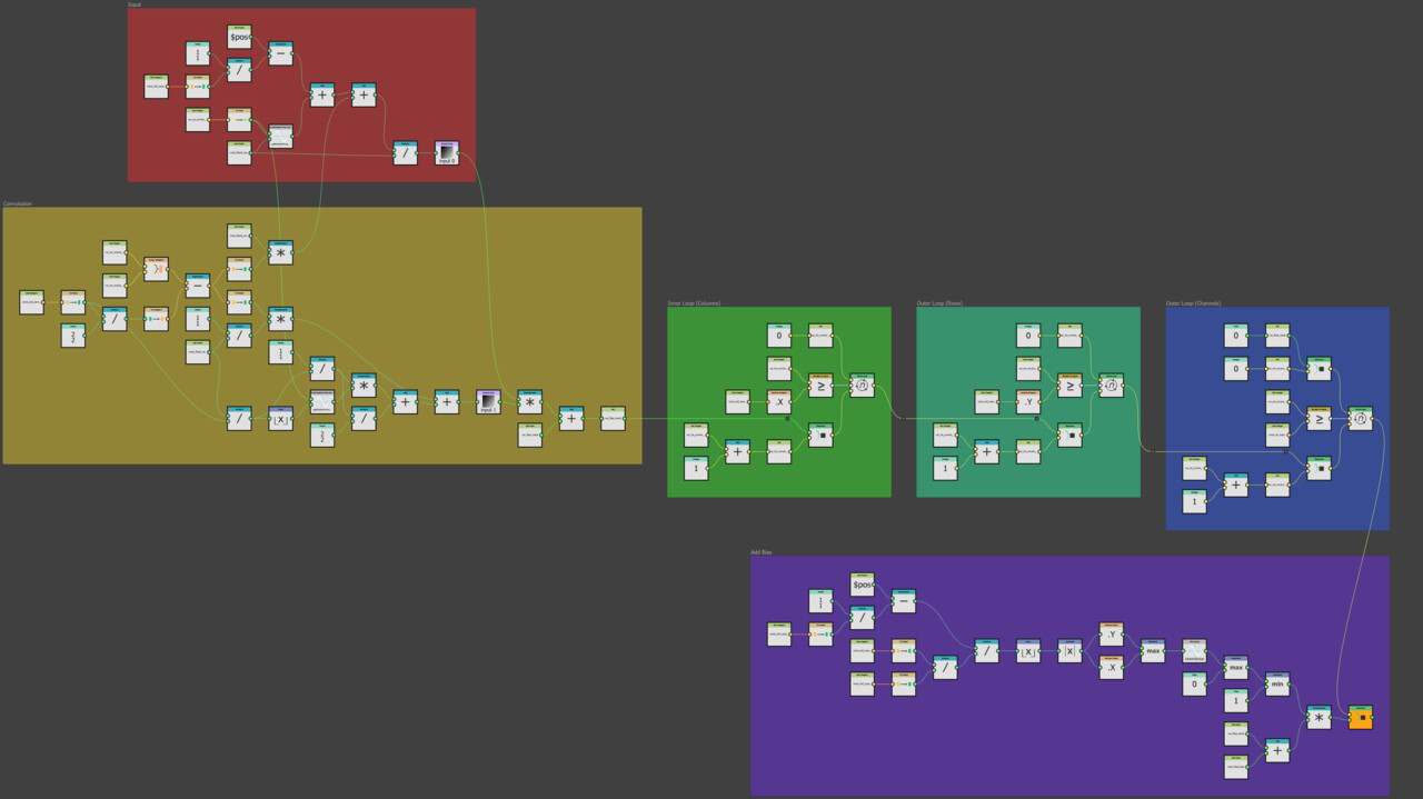
Here is the full graph inside the Pixelprocessor, I will explain the different sections step by step

First we choose an angle, where the result of the tangens is a "nice" rational fraction, convert this into a Float2 and use the ArcTangent2 - Function to get the angle in radians.

Next we calculate h' and w' which is the scalefactor for the texture at that angle, for this we multiply h_w and w_w by the reduced fraction of our input angle.

Then we calculate the rotation at this angle and multiply the result by the scale-factor from the previous step.

This gives us the correct scaling and rotation of the texture, so we use this Float2 as sampling position.

I hope you enjoyed this short tutorial on how to tilesafe rotate a texture in Substance Designer. If you want to look into the .sbs or just use this tool, you can download the finished node from my from a google drive here.

Stay healthy and creative

Marco

Water Ripples in Substance Designer

Tutorial / 11 January 2021

A water ripple is basically just a some kind of radial wave-function moving away from the center, while loosing energy (height). But is it really that simple? Let's take a closer look at a Reference Photo. 

It seems, that at the ripple has one big wave in the center and while moving away from that point, it looses energy (height) and gains frequency. I read a little bit about the special behaviour of water and surface tension and got a lot of articles discribing, how a ripple forms. What is the difference between a ripple and a wave? At the end of the day I had all the math and physics for building a water ripple.

I experimented with some exponential increase of the frequency and at the same time, some other exponential decrease of the amplitude all applied to a sine function. I searched for some constants and stumbled over a YouTube-Video and more important a link to an over 20 years old coding-website, which only exists in the webarchive (2D Water) by Hugo Elias who found that algorithm somewhere else.

The algorithm he discribed was so elegant and simple to implement in designer that I just tried it and the result was fantastic. Let's take a look at my implementation in Designer and see how the algorithm works.

The Main-Graph (water_ripples_buffer.sbs)

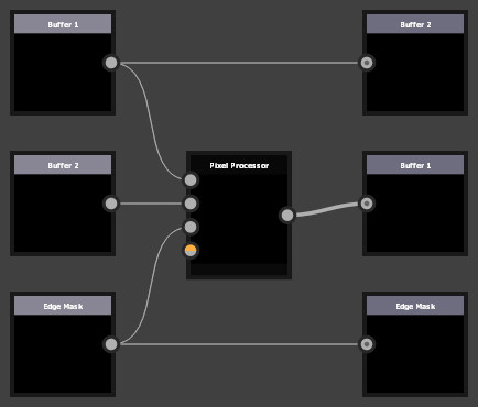
The Main Graph is basically just a Pixel Processor with three Input- and Output-Nodes. The important thing is, that the Pixelprocessor - Output is connected to Buffer 1 - Output and Buffer 1 - Input is connectded to Buffer 2 - Output.
The rest of the magic happens inside the Pixel Processor.

This is the whole Pixel Processor Graph, separated into three sections, Output-Conditions (green), Neighbour-Values (red) and the sum (blue).

First we have a look at the Output-Conditions.

These three conditions, influence the behaviour at the image-boundaries or the custom-mask. The left condition is only true for non-edge-pixels, so the reflection at the boundaries happens. The next condition is true as long as the custom-mask input has a value below 1, that creates the iteraction with the mask and the reflection-effect at the edges. The last condition takes care of the case, where the ripples just seamlessly tile at the edges.

The next section, we'll have a closer look at, is the Neighbour-Values (red) 

These four frames take care of the main-part of the algorithm

FOR EVERY PIXEL IN THE INPUT BUFFER 1:
  ADD UP ALL VALUES OF ITS DIRECT NEIGHBOURS (LEFT, RIGHT, TOP, RIGHT)

After adding up all these values, we take a look at the final step

- DIVIDE THE SUM OF ALL THE NEIGHBOUR-VALUES BY 4 (AVERAGING THE VALUES)
- SUBTRACT THE INPUT BUFFER 2 (SUBTRACT THE PREVIOUS STATE)
- MULTIPLY BY SOME VALUE LOWER THAN 1 (ABSORBTION)
- CHECK THE OUTPUT-CONDITIONS
- OUTPUT THE RESULT

And this is what happens, when there is some kind of collision-object (custom mask)

This is the result rendered in blender cycles @ 512 Samples


Thank you for reading and don't forget to download the free generator from my store

stay safe and all the best Marco

MyTips #2 - String to Pattern

Tutorial / 14 December 2020

Inspired by Martin Schmitters (www.artstation.com/martinschmitter) QuickTips, I began to do some of my own.

Here another one on how to create complex patterns with just a Text-Node.

I hope you like it and I'll make some more in the future. Feedback very welcome.

All the best Marco

MyTips #1 - Welding

Tutorial / 03 December 2020

Inspired by Martin Schmitters (www.artstation.com/martinschmitter) QuickTips, I began to do some of my own.

Here is my first Tip on how to create welding in Substance Designer.

I hope you like it and I'll make some more in the future. Feedback very welcome.

All the best Marco